Since getting into music technology I have always had an interest in analogue equipment, and having something tactyl to work with. Having also an interest in electronics, home fabrication and DIY type projects, I soon got into things such as circuit bending, electronic equipment repairs/mods, and also making basic audio equipment such as amplifiers, mixers and pickups.
The key motivations of my DIY projects are to make interesting pieces of gear that I can use for creating music. One project that I made a few months ago was a basic triangle wave oscillator, inspired by Look Mum No Computer (https://www.lookmumnocomputer.com/projects/#/simplest-oscillator/). After playing around with this design, I made a few sample recordings of the oscillator, which I then made into a sampler instrument that could be played within the software. However, having my oscillator now restricted to software gave me the idea of creating an oscillator that could be tracked using circuitry and physical keyboards, thus keeping the oscillator as a physical instrument. With this I immediately became interested in eurorack modular synthesis, and the 1v/oct system that they use in their modules.
Therefor, my plan for this project is to expand my knowledge of electronics and synthesis, by designing a voltage controlled oscillator (VCO) that can be tracked using the 1v/oct standard.
This project will consist of gathering research of electronics, and similar existing designs, in order to design a circuit of my own. With my design I may then go on to source the components needed to create my product in the future.
In electronics an oscillator is a circuit that produces a repetitive AC signal across its output terminals. Depending on the circuit design, the oscillator may produce constant or variable wave shapes, frequencies and/or volume (1). In essence, oscillators are circuits that generate wave shapes that can serve musical purposes, when controlled for pitch and volume.
In musical purposes it is desirable to have variable frequency and volume controls, as well as wave shape controls if the circuit is able to produce more than 1 type. These functions can be controlled using various electronic components and techniques including: adjustable capacitance or resistance; vactrols/photoresistors; or even other oscillators (2)(3). For my project, however, I plan to just modulate pitch using control voltage (CV).
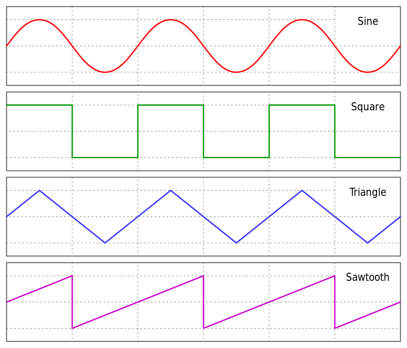
There are a few main types of wave shapes that oscillators produce, these are named and categorised below:
Sine wave oscillators produce a sine wave output.
Relaxation oscillators produce Square waves and rectangular pulses.
In the physical world, sound is produced by a vibrating object that causes the medium surrounding it to carry that vibration (i.e air, water, solid structures). Sound vibrations in air are explained as longitudinal waves, that cause areas of high and low pressure- also known as compressions and rarefactions- these vibrations travel in parallel to the direction of the wave. In human hearing, the ear is a receiver that can translate the changes in air pressure into what we perceive as sound. (4)
In electronics, however, waves are not longitudinal traveling sound waves- instead they exist as transverse waves, whereupon the oscillations occur at right angles to the direction of energy transfer. This concept can be visually represented in the image above, whereupon the Y-axis represents amplitude (positive and negative amplitude is measured from the horizontal line in the centre), and the X-axis represents time (figure 1). (5) However, physical and electronic oscillations do have shared characteristics listed below:
Amplitude (A)
Maximum displacement from the equilibrium position (magnitude/intensity of oscillation, which in the sound wave example is proportional to loudness).
Frequency (f)
Number of waves (full cycle vibration/oscillation) passing a point per second. Hz. (in sound waves, frequency is perceived as pitch- thus the higher the frequency, the higher the pitch).
Period (T)
Time for one complete wave oscillation. T=1/f
Wavelength
Distance between two consecutive points that are in phase (i.e. distance of peak to peak).
(5)
Oscillators are the fundamental sound generators for electronic synthesis, making them an integral part of synthesised music. Synthesisers themselves exist in many different forms, but most often, the wave generator section acts as the first stage in the signal path- from which the wave forms they produce can be manipulated by other parts of circuitry further down the path. Different synthesisers often have very simple wave generators within them, perhaps only capable of producing one or two types of basic waveforms, however, it’s other parts of synthesisers such as filter, envelope and/or fx sections that are able to turn basic waveforms into more complex sounds. For this project though, I am focusing on building just the oscillator section in a modular fashion, so that my circuitry may be compatible with other designs and projects in the future.
Oscillators in their most basic form, are just circuitry capable of producing a repetitive AC output. However, this is usually too basic for use in synthesis, as we want to be able to at least control the pitch, and sometimes wave shape. Therefore synthesis manufacturers and product lines, have developed different ways in which these parameters can be controlled:
Wave Shape-
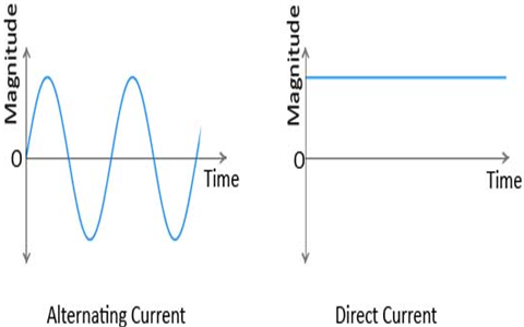
As mentioned previously, an electronic wave is created when there is a repetitive AC (alternating current) signal across the output terminals. However, the wave shape itself its characterised by the relationship of the output current and voltage over time. To understand this better, we have to first understand that alternating current, unlike direct current, is able to periodically change the direction of its flow of charge. This is managed by the direction of current and voltage changing in synchronisation with one another. Below is an image depicting the difference between AC and DC, with the Y-axis displaying the magnitude of voltage OR current, over time.
From the graph we can determine that for DC, the voltage and current remains fixed over time, whereas for AC the voltage and current are constantly changing direction in a sinusoidal motion. It must be noted that when the change of charge direction occurs, the voltage/current passes the zero-crossing point, and becomes either positive or negative- this is directly related to the change in direction of energy transfer in sound waves which is why AC can be transferred into sound waves, and DC cannot.
Returning back to creating different wave shapes, it must also be noted that alternating current doesn’t have to be sinusoidal. Different circuits can cause AC to create many different wave shapes, including all of the ones displayed in Figure 1. Synthesisers often include many of these different circuits, which can be switchable.
Pitch
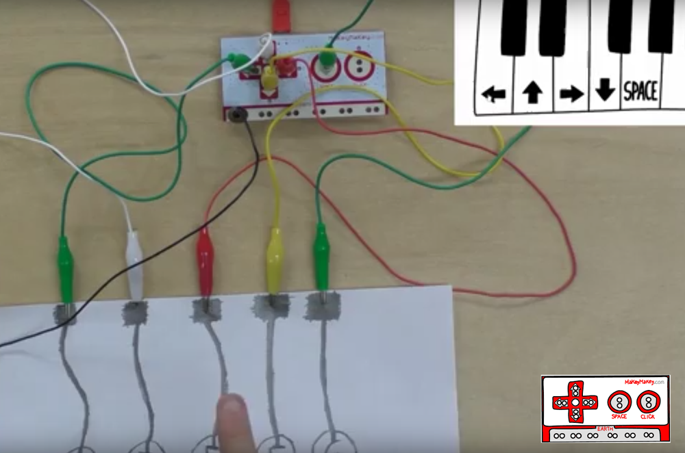
Pitch can be controlled in many different ways, and choosing the most suitable one is entirely dependant on the application of the VCO. The most common way to control the pitch is to use a keyboard that will cause the VCO to play discrete musical notes- however, VCOs that are used in more abstract ways may be tracked using other methods such as potentiometers, photoresistors (LDR’s), or even homemade variable resistors using conductors such as graphite from a pencil drawing (Figure 3 below).
For my build though, I want to be able to track pitch using 1v/oct control voltage, as this is one of the most common and accessible methods. 1v/oct CV can be outputted from many different compatible products such as keyboards, sequencers, push controllers and also some other synthesisers/synthesiser modules (especially eurorack).
Creating a 1v/oct VCO is different between circuit designs, and can become very complicated. However the basic idea is that for every 1 volt rise to the CV input of the VCO, the pitch doubles in frequency, thus going up an octave. This relationship, isn’t as simple as it sounds however, because you are taking a signal that is linear, and outputting a signal that is exponential. This must be the case because the fundamental nature of human hearing is logarithmic, thus the frequency difference between octaves will be a factor of 2, and not a fixed number. Therefor, in order for 1v/oct CV to work, there must be a linear to exponential voltage converter that occurs before the CV reaches the VCO. Below is an example schematic of an exponential voltage converter, used for synthesis. (7)
Luckily for me, the internet is full of many different websites dedicated to synthesiser circuit designs- many, with in depth electronic theory included. One of my main inspirations for starting this project actually came from a video posted by ‘Look Mum No Computer’, for a simple to build triangle wave oscillator (https://www.lookmumnocomputer.com/projects/#/simplest-oscillator/). The flaw with this design was that the oscillator was not built to be tracked at 1v/oct, and creating additional circuitry to do this could be quite difficult.
With this, I decided to research how existing synthesisers went about creating 1v/oct VCO’s, and whether I could use this to inspire my own design. I came across the website ‘Secret Life Of Synths’, wherein there was a section dedicated to famous synthesisers VCO’s (http://secretlifeofsynthesizers.com/the-vco/) . It was here that I discovered that back in the 70’s at the breakout point of synthesis, engineers had to overcome many electrical challenges in designing stable VCO’s such as: finding ways for the VCO to range around 8 octaves; producing relatively low frequencies (even below 20Hz for LFO’s); be able to stay in tune across the audio range when controlled by a standardised control voltage (1v/oct); and also minimise the effects of temperature on the tuning. The result was a few precision VCO chips, capable of tackling all of these existing problems in one compact and affordable way. One of the best known and loved VCO chips was the Curtis Electromusic CEM3340, and was used in such synths as the Sequential Circuits Prophet 5, and the Moog Memorymoog. The CEM3340 actually contained most of the oscillator circuitry within the chip, including: sawtooth, triangle and pulse outputs; a PWM input; hard and soft sync inputs; an integrated exponential converter that uses 1v/oct; an FM input; and also temperature compensation. The impressively small size of this chip also enabled manufacturers to place several chips within synthesisers, and thus grow the polyphonic synth movement. (8)
For my project I have decided to use the CEM3340 chip for my design, as I have been inspired by it’s uses in other synths, and it’s advanced capabilities. In order to design my VCO, I first took a look at the CEM3340 data sheet found here https://cdn.hackaday.io/files/1605386868457792/CEM3340.pdf (9) The datasheet covers the function of each pin, and also gives an example schematic. For my design however, I have made variations to this schematic. I have used the open source software ‘Fritzing’ to design a digital PCB for my build, and I have included screenshots of this project below.
The first step of my design was to open the ‘new parts editor’ in fritzing, which allowed me to design the CEM3340 chip in the software, as it was not already available in the components library. Below, the 2 screenshots show the data I wrote up for the chip, including a description of the function of each pin.
Once I had created the CEM chip in fritzing, I then went about arranging the PCB design with all of the other components needed for the build. My first step was to route the 12v mains supply to the necessary points of each of the 3 IC’s (the CEM3340 and 2 dual channel op-amps). The 2 dual channel op-amps are used to gain and condition the outputs of each of the wave shapes from the CEM3340.
Once I then had the power and the wave shape outputs routed, I designed the fine tuning section, which is taken from pins 1 and 2- and also the course tune section which is controlled between pins 15 and 16. Both of these sections use resistors and potentiometers to control the tuning. Finally I routed the final 3.5mm jack terminals, including CV in, PWM in, and hard and soft sync in- and connected all other necessary components such as resistors and capacitors between these connections.
The pink wire section shows where you should break the connection of the PCB by scratching out the metal strips. This will ensure parallel pins of the IC’s are not connected.
Over the course of this project I have done extensive research into areas of electronics that can be used to serve musical purposes- and as this is an interest of mine that I actually use to evolve my musical practice, I feel that this project has been very beneficial for that. Much of the research I have done, in fact, has not been directly related to the VCO build and thus not documented in this project, but has been very useful in widening my knowledge of electronics and synthesis.
Unfortunately, I am still in the testing stage of the physical build and am not able to demonstrate the finished product working. I have had a few complications with the physical build so far, and I feel that it may not be working because the CEM3340 chip that I used, was not actually purchased from the original manufacturer and is therefore a knock off. Hopefully I will be able to get hold of an original one soon to test this theory, but before hand, I am first testing connections between components to check that this isn’t a problem that could be an easy fix.
However, I am excited that the very ideology of this whole build is ongoing, and so I look forward to improving my knowledge and skills over time.


